This could be a nightmare for the boaters. Go to a store that sells paint and get a can of xylol xylene paint thinner.

Premium Photo | Close-Up Detail Of Old Dirty Painted Yellow Natural Gas Pipes With Welding Seams
With the engine off, get close to your carburetor and sniff.

How to deal with old gas lines. A slow, steady gas leak can damage appliances or other home fixtures. Place the tool into hot water for 10 min and measure the water temperature. In addition, covers a leak caused by a disaster (like a blizzard, lightning or hails) that damages the system or its gas line and causes a leak.
This will require either removing the valve or valve core. Since clogged pipes are common issues in older homes, it’s tempting to use chemical drain cleaners to clear the clog. Ethanol free gas will be good for a year.
Research the nearest disposal center for old or contaminated gasoline. The first step is to turn off the gas supply at your gas meter. John ibbotson, chief mechanic at consumer reports, says that.
The main reason metal fuel lines fail is corrosion, but most corrosion starts when abrasive materials start to remove the paint or coating on the line. Why metal fuel lines fail. Inspect and clean mating surfaces of gas feeder and valve.
In order to determine if the gas is tainted or expired, transfer a small portion of it in a glass object or canister. A gaslighter will try to destroy your perception and the world you built for yourself. The gas leak is due to an old leak.
Taking care of your physical and emotional needs probably won’t do anything to. If it’s stored business fuel, it’s most likely going to be diesel fuel. How to drain old or bad gas from your lawn mower and/or most small engines.
Go grab your old gasoline, and pour it down on a hole. After doing so, you have to bury the mound appropriately. That being said, we will now see how to deal with old gas in the boat in a detailed way.
This can occur at a mounting bracket or from debris kicked up from the tire. Make sure the gasoline is in an approved container (again, that does not include plastic bags or random buckets ). Search online for “hazardous waste disposal center” in your county, city, or state.
The valve that regulates the flow of gas will be connected to your pipe at a right angle, but can sometimes be difficult to locate. Avoid further discussion by changing the subject or leaving the room. Crack open gas cylinder valve and close.
Due to the combination of old gas + new fuel, it. The high acidity levels in drain cleaners can accelerate deterioration in old metal pipes. Then, transfer fresh gasoline into another.
Read the pressure from the gauge on the tool. Diesel fuel has the same problems except for the phase separation. Position gas feeder on new gas cylinder and tighten yoke screw.
So that leaves consumers who face the issue. When it comes to dealing with “old gas”, that’s largely a consumer problem. In almost every case, old gas is not an issue.
Chill the gasoline and tool on ice for 30 min. Really old fuel will turn into varnish . In 2017, gas leaking from an abandoned gas pipeline ignited, causing an explosion in a colorado home that left two dead and one seriously injured.
One of the most important defenses on how to deal with gaslighting in a relationship is to keep your individual identity. What the policy doesn’t cover: Investigators later discovered the line was still connected to a nearby gas well.
It can also contribute to the internal rusting of the gas lines and tank. Very few businesses store gasoline for sizeable periods of time. Pour in about a quart or so, distribute.
If your fuel system has one of those schrader valves for pressure testing, you can tap into the system there. Using old gas with new fuel can save a lot of money, but it comes with a price. You don’t have to light it up, it’s enough to fume the nest out.
Follow their instructions, but typically you’ll have to do something like this: Old fuel will go bad. This varnish will coat the inside of your carburetor and fuel lines.
(too much xylene per gallon might shorten the life of you motor and cause it to burn or leak oil). In general, yes, one can use old gas in the boat. Determine whether the gasoline is tainted or expired.
We also take apart the carburetor bowl and jet to drain the gas and to i. Compare the pressure and temperature to a table that comes with the tool. When the fresh gas mixes with the older gas, the motor will operate properly.
Faced with such risks, the canadian government set up a system that requires pipeline companies to estimate the cost. It can also coat the inside of your fuel tank. Add up to 3 ounces of xylene per 10 gallons of gasoline.
This section deals with all the facts and information related to the usage of old gas in the boat. Remove the fuel pump relay, and short the two signal pins in the fuse box. Be sure to use a chain or cable to secure the new cylinder properly.
Check with your local fire department. After a short amount of time, it will kill then queen ant, and the entire nest dies along with it. Gas that sits does slowly go bad.
An easy way to detect for a varnished fuel system is to sniff with your nose. Take your vehicle for a test drive. A vehicle’s fuel lines are routed so that, in case of an accident, the.
Pour the fuel into the tool and close it. This product is very strong and will dissolve any fuel residue (gum, varnish, etc.), while also carrying away any remaining water. Call ahead to the waste disposal site to check hours, rules, and what else they take—y ou may be about to.
It’s important to know how to dispose of old gasoline due to its flammability, which could pose various safety hazard risks. To stop someone from gaslighting you, try not to get into an argument with them. Call your county or city waste management agency and ask where gasoline goes.
However, gas that sits, even for a few months can be redeemed by topping off the tank with fresh gas. Using old gas is acceptable and possible, but with some conditions. This insurance will pay if there are explosions by leaks.
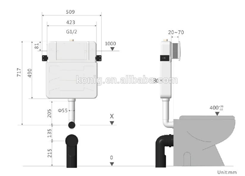
A flush valve is the toilet part at the bottom of the tank through which water flows from the tank to the bowl during flushing. This can be a tricky situation especially if.
Cistern Flush Tank Plastic Toilet Flush Tank Plastic|Water-Saving Tank|Yuyao Homewell Plastic Industry Co.,Ltd. Bathroom Accessories Toilet Fill Valve Toilet Flush Vale Toilet Water Tank Accessoies Toilet Plastic Water Tanks Toilet Repair Sets

Kohler highline classic toilet the best chair height.
Toilet flush tank. Get contact details & address of companies manufacturing and supplying flush tanks, toilet flush tank, toilet flush across india. To get rid of a lot of water, hold the handle down until all the water is gone. 2 pcs toilet push button rods, 38mm universal chrome dual flush toilet push button high pressure pumps accessories for toilet closestool toilet flush valve repair kit (silver) toilet tank.
After use, the bowl is emptied and cleaned by the rapid flow of water into the bowl. The first step in making repairs to the parts of a toilet tank is to determine which toilet. This is one of the latest flushing systems on the market.
The #1 component that wears out in a toilet’s flush valve is a piece known as a flapper. The main function of a toilet tank is to supply the bowl with enough water to flush the toilet. The toilet will not flush if the flush valve chain has gotten detached from either the flush lever or the flush ball.
3) toilet fill valve (diagram). To find the leakage locations of the toilet, first of all, take off the lid from the toilet tank. The float cup is connected by a metal rod to the arm of the ballcock.
Stir the water in the tank for about half an hour. The toilet cistern is the part that holds water at the back of the toilets. Use a microfiber cloth or sponge to drain the remaining water in the tank.
4.0 out of 5 stars. The ideal distance to keep your toilet away from other objects is 15 inches. Water rushes from the tank into the toilet bowl.
Remove the bolt cap & remove the nut from the bolt holding the toilet on. American standard champion white standard height toilet the best elongated. Pushing down on the toilet flush handle or lever (or on some toilets lifting.
When you flush the toilet: Do not flush the toilet until it is half an hour. Unscrew the toilet connector for the toilet and/or the wall.
A typical flush tank toilet usually holds several liters on its tank. Adjust the water level in the tank using the float if the toilet isn’t flushing well. Are there common water tank leaks?.
This universal design fits most toilets. What happens when a toilet is flushed: A toilet has 2 main parts, a tank and a bowl.
*this is a tvalve because of the bidet* | 3. Attach chain or strap of toilet flapper ball to new flush lever and adjust as needed. The handle tugs on the chain, which opens the flush valve.
Water flows from the tank to the bowl via the flush valve. After half an hour, check the condition of the water. To allow full pressure for the.
This toilet tank drain is a great toilet accessory. Make sure the chain isn’t too slack so the flush ball lifts when the toilet is flushed. How the toilet tank works.
The tank is usually mounted on top of the bowl so that water can flow from the tank to the bowl using gravity during flushing. The toilet fill valve refills the tank. Find here flush tanks, toilet flush tank manufacturers, suppliers & exporters in india.
Insert new flush lever into toilet. When the tank’s water rapidly drops down into the bowl (upon a flush), the pressure causes the bowl’s waste water to go down the drain. For a modern look, you can keep your flush tank 18 inches away from the other part of your bathroom.
When the water enters the bowl, it exerts a force inside the bowl therefore creating a siphon effect at the toilet trap. Empty the toilet tank by flushing the toilet. The toilet flush button releases the water through the toilet flush system to wash the content of the toilet bowl into the septic tank.
The drop in water level is sensed by a. When the toilet tank water level reaches the proper level, the float closes. Flush valves are attached to the toilet tanks by a lock nut from underneath the tank.
There are two major toilet parts in the tank. The threads loosen in the opposite direction. After releasing the handle the flapper seals the flush valve allowing the tank to refill in readiness for the next flush.
Empty the water into the toilet tank. A typical flush toilet is a fixed, vitreous ceramic bowl (also known as a pan) which is connected to a drain. Then apply some drops of food coloring or a few dye tablets.
Shut your valve on the wall to off & empty the tank by flushing the water down. This flush and toilet flap can help solve these common problems. Problems with your toilet flush system could prevent your toilet from flushing properly.
The double cyclone flushing system utilizes only 1.28 gallons of water per flush, but it still has the power of a full 1.6 gallons per flush. 3 basic operations flushing the toilet opens the flush valve: Actually, this system has been introduced by the toto toilet brand.
As the water level in the tank falls, so does a device called a float cup, which floats on the tank water. The toilet tank's function is to hold a quantity of water until you flush the toilet, at which time the water in the tank rushes down through an opening in the bottom of the tank and into the bowl, forcing waste out of the bowl and into the home's drain and sewer lines. When it is activated, this blockade is lifted.
You can measure the distance from other parts of your bathroom like the wall, vanity or shower enclosures. Names of “toilet tank” parts: It is used for quick and easy installation, solving common problems and directly replacing faulty or outdated models.
One of these devices—called a ballcock—is connected to the water supply and controls delivery of water to the tank. With the carrier concealed in the wall, only the bowl and actuator plate are mounted to the wall, resulting the sleekest design that is incredibly easy to clean. Attach locknut to flush lever and tighten it down to toilet tank, remember the reversed threads.
Following diagrams is fairly simple, but making use of it inside the scope of how the device operates is a new different matter. Injunction of two wires is usually indicated by black dot on the junction of 2 lines.

Wiring - How To Wire Up Single Phase Induction Motor? - Electrical Engineering Stack Exchange
With the main winding’s connected in parallel, the line voltage is usually 240.

Single phase motor 2 capacitor wiring diagram. Split phase single value capacitor electric motor (dual voltage type). Capacitor start capacitor run induction motors are single phase induction motors that have a capacitor in the start winding and in the run winding as shown in figure 12 and 13 wiring diagram. Single phase motor capacitor connection wiring diagram motors weg standard product catalog doerr lr22132 w22 a jm 5 hp 2p 182 4jm 1f 208.
How to wire single phase motor with capacitor. However yellow is the start switch blue is the auxiliary winding and red is the main winding. See the wiring diagram above.
Weg single phase motor wiring diagram with capacitor on weg 7.5 motor wiring diagram. You will find out how to identify to main and auxilliary winding and. All circuits are the same :
Capacitor run single phase induction motor scientific diagram. Capacitor start induction motor its equivalent circuit of a single phase run motors few words about cs diagram starting applications voltage cap schematic and capacitors wiring ac electrical for csir electric what. Single phase motor connection diagram capacitor run induction cap start motors wiring of a double electric circuit what does do wire power electrical wires starting voltage an overview help with 3 ways to troubleshoot ac few words about cs technology its supply practical.
During starting, as the capacitor is connected in series with the starter winding, the current through the starter winding is leads the voltage v, which is. Single phase enclosed baldor com. Run capacitor at the top, start capacitor at the bottom.
Single phase motor wiring diagram with capacitor november 20, 2018 april 12, 2020 · wiring diagram by anna r. Capacitor run single phase induction motor scientific diagram. To properly read a electrical wiring diagram, one offers to learn how the particular components in the system operate.
3 phase 6 lead motor wiring diagram. This gives the following circuit diagram. Read wiring diagrams from bad to positive plus redraw the circuit like a straight collection.
Have the right tools handy just like any other diy job, you want to. The best advice is not necessarily only look from the diagram, yet understand how the components operate when in use. Single phase motor wiring diagram with capacitor baldor single phase motor wiring diagram with capacitor single phase fan motor wiring diagram with.
Vfds for single phase applications keb. Single phase motor wiring diagram with capacitor wiring diagram is a simplified all right pictorial representation of. This gives the following circuit diagram.
Learn how a capacitor start induction run motor is capable of producing twice as much torque of a split. Dc ff a hp 1/6 time cont ratio 20;1 rpm. Single phase induction motor with shorted coils of auxiliary winding scientific diagram.
Capacitor start 220v single phase motor wiring diagram. 2 phase motor connection with capacitor.if the motor was originally connected in y and you reconnect it in delta a 380v motor will now be 220v or a 415v motor 240v and you will get full power but the torque characteristics are not good as the current through the capacitor does not increase with load. Single phase capacitor start motor wiring diagram source:
A motor with a start and run capacitor and a start and run. Capacitor start 220v single phase motor wiring diagram source: Voltage, ground, solitary component, and buttons.
All the information is there. Why capacitor is required for single phase motor electrical4u. Yc series single phase dual value capacitor start induction ac electric motor china iec made in com.
Terminal connections for capacitor start single phase motors. When you use your finger or perhaps follow the circuit along with your eyes it s easy to mistrace the circuit. Single phase motors are used to power everything from fans to shop tools to air conditioners.
There are a number of different construction methods used, but the basic principle is the same. China yc double starting capacitor single phase electric motors motor. Capacitor start motors diagram explanation of how a is to single phase motor bright hub engineering.
Ac single phase motors part 2 double capacitor induction motor connection start diagram electric wiring of a diagrams 3 ways to troubleshoot with starter winding types run ecn electrical forums starting applications capacitors for 220v uk momentary switch mains reverse switching. Because it is designed for continuous duty, it has a much lower failure rate than a start capacitor. 230 volt single phase motor wiring diagram.
Bodine electric company is a leading manufacturer of fractional horsepower gearmotors, motors, and motor speed controls. The wiring colours to the motor suggest that this is a three phase motor, just to confuse me. Century fan motor wiring diagram.
Capacitor start run motor fig 13 single phase induction cap motors a starting voltage test the winding resistance of equivalent circuit few words about cs schematic diagram electrical for csir and capacitors potential relay to cscr what is types electric split hermetic windings ac part 2 quality wiring an. Single phase motor wiring diagram cap start run motors a through 3 electric power electrical wires starter to connection induction technology and controls of diagrams ac voltage reverse switching control sd capacitor type contactor for direction change groschopp magnetic practical machinist largest split learn how double ways troubleshoot with. Terminal markings and internal wiring diagrams single phase polyphase motors meeting nema.
Click here to view a capacitor start motor circuit diagram for starting a single phase motor. Click on the image to enlarge and. Wondering how a capacitor can be used to start a single phase motor.
Weg 7518es1b56 s 0 75 hp 1800 rpm tefc 56 frame factory new motor at dealers. A schematic diagram of capacitor start and run type spim scientific. Capacitor start 220v single phase motor wiring diagram source:
For instance , if a module is usually powered up and it sends out a new signal of half the voltage and the technician will not know this, he would think he has a challenge, as he would expect the 12v signal. Baldor electric general purpose motor 10 hp capacitor start nameplate rpm 3 450 voltage 230v ac 38g309 cl3711t grainger.
A run capacitor uses the charge in the dielectric to boost the current which provides power to the motor. It makes funny bumping/shuttering sounds and you can hear the rpm of.

Buy 5 Mfd Capacitor 370 Or 440 Vac 5Uf Oval Run Capacitor For Fan Motor Blower Condenser In Air Handler Straight Cool Or Heat Pump Air Conditioner And Pool Pumps By The
The start capacitor is responsible for dispensing the electrical push needed to start the hvac motor rotation.

What does the air handler run capacitor. In air conditioners, there are “dual run capacitors” that serve two functions: An ac capacitor is a small cylindrical, oval or square shaped device inside your heat pump or air conditioner that supplies or stores energy. You can use a capacitor tester to check for this, but as a capacitor is the most common failure in an ac unit and we have the most units in the store.
A run capacitor uses its charge to boost the current that provides electric power to the fan motor. The ac air handler then blows the air out through the ducts and distributes it throughout the home. Locate the side panel of your ac unit.
These hard start capacitors can be used on heat pumps & air conditioners. Simply put, air handlers are devices used to create conditioned air, and move that air throughout a space. Most air conditioners have two capacitors, one at the condenser and one at the.
Run capacitors are more common and are responsible for keeping the motor running until your home is comfortably cooled. Hello, new to the forum. Sometimes while the inside air handler fan is running, the fan seems to bog down and wants to stop running and if left alone, it will stop completely.
Please observe those factors to make sure you get it right, especially when wiring a. Air handlers come in many shapes and sizes, but commonly take the form of a fan, filter, and coil enclosed in a large metal box. Typically there are four 5/16 hex screws that attach the side panel to the rest of the unit.
In many outdoor units, there's a start capacitor, which helps the ac get going when there's a call for cooling. Use the appropriate bit with a bit driver to remove the screws. A hard start capacitor (also referred to as a hard start kit) is simply used to help the compressor on startup to overcome the increased pressures in the refrigeration circuit.
It typically can be found in the garage, attic or closets. The other sends power to the compressor. Capacitors play an integral part in the running of a home.
A telltale sign that one or both of these components has failed is when your air conditioning system’s fan runs normally, but the air is not heating or cooling. To test the fan motor on your air conditioner, you’ll have to do a continuity test. However, with a clear understanding of what each type of capacitor is, this confusion can easily be resolved.
The run capacitor in your ac is used to store. Think of these two parts like riding a bicycle. Visually, if the capacitor is swollen then you need a new one.
Then the compressor should begin up once more. One capacitor provides power to the fan motor. There are a few factors that play heavily into the lifespan of your capacitors, though.
It stores electricity and sends it to your system’s motors in powerful bursts that get your unit revved up as it starts the cooling cycle. We have all been guilty of this at one time or another weather we admit it or not.in this video i find a great example of exactly why you should never just r. Once the cooling cycle begins, the run capacitor takes over.
The capacitor and contactor are a team. Either the outdoor fan does not run, the compressor does not run, or both the fan and the compressor do not run.you pull the disconnect and disconnect the power to your outdoor air conditioning unit. In ac units, there are dual run capacitors.
The differences between a run capacitor and a start capacitor can be bewildering. Your air conditioner may very well comprise several different capacitors, together with the compressor motor run capacitor, the skin fan motor run capacitor, the indoor fan motor run capacitor, and the beginning capacitor. Place the screws in a secure location so as not to lose any.
The capacitor and contactor work together in your air conditioner or heat pump to help power the fan and compressor. Once your ac is up and running, the capacitor reduces its energy output, but still. In phoenix, perhaps one of the most damaging elements for air conditioner capacitors is the heat.
Once the system has started and is operating, the run capacitor takes over and provides the extra power to run the air conditioner for long periods of time. The air then passes over the cooling elements. The ac air handler pulls air it in through the intake vents.
However, your system might just have one capacitor in the outdoor unit, and certain models even have a capacitor for the indoor blower motor. I have a rheem split unit ac. These are not used on compressors that utilize start capacitors.
A capacitor is an electrical component that stores electricity to deliver a large charge when needed. Capacitors fail every day — they do a tough job and, unfortunately, their work takes a toll. There's also a run capacitor, which keeps the system going after it starts up.
How to test your ac fan motor. One provides power to the fan motor (just like in the furnace) and another sends power to the compressor. Many air conditioning systems, as well as heat pumps, use a dual capacitor.
Unscrew the bolts and remove the side panel. Here are some things that you can look for if your capacitor is bad.the air conditioner outdoor unit will not come on. When the air conditioner is running, both capacitors create and store energy for the push for the next cycle.
When we think about an air conditioner, this charge is needed to start the condenser and condenser fan. The ac air handler is often located inside the home. An ac capacitor provides the initial jolt of electricity your air conditioner’s motors need to run successfully.
Run capacitors are more commonly used in air conditioning systems than start capacitors. They can also be useful to help keep the system running. It is used to maintain a charge.
Valve actuator the actuator operates the stem and disk assembly. Danfoss offers a comprehensive range of control valves and actuators for virtually every application:

Actuator Untuk Tiga Arah Katup Pengganti Westen Pulsar Boiler 3 Way Valve Actuator Motor| | - Aliexpress
This is because they store domestic hot water in a cylinder rather than sending it straight to the taps.
Boiler actuator valve. Most forms of valves, including ball valves, butterfly valves, and. In the gate valve the closure membrane is a metal gate. But actuator performance is commonly measured in terms of reliability only and in many cases, actuator problems tend to be addressed only after a serious or complete failure occurs.
A basic flow control valve opens and closes to adjust the rate of water in the boiler. Pressurized steam enters the valve through the nozzle and is then threaded to the boiler. During fuel oil operation this valve operates as a back pressure control valve keeping the.
We also stock the vokera 20024841 three way valve actuator, a specialised directional water mechanism that only appears in combi boilers and allows the water flow to be diverted across the house or building. If you have a combi boiler then it will have a diverter valve. 4.0 (1) | contact supplier.
In other designs, a yoke mounted to the bonnet supports the actuator. Order) cn shanghai intelsheng international trading co., ltd. These valves are usually used in on/off condition.
Domestic hot water and primary micro switches. The spring is the pressure controller. By staff writer last updated march 26, 2020.
At the heart of boiler control and efficiency is actuation. Vgf flanged globe valve families have ansi 125 and ansi 250 designs. These valves are actuated by using compressed air.
They can be motorized, hydraulic, or even solenoid type valves. The flow control valve on a boiler regulates the flow of hot water to the system. Basically the valve actuator (honeywell vc6012) sometimes does not switch over to heat the water when there is demand for hot water and then sometimes it does not switch back.
These valves are available with brass or stainless steel trim. There is too much condensation. The spring return units have broken springs.
The system or actuator filter is blocked or clogged. Under this, you will see the actuator which is held in place by. Move the manual override lever to the manual position then remove the cover.
Plus full boiler fault diagnosis for the following: Oct 09, 2019 · responsive and repeatable control of the boiler feedwater recirculation (bfr) valve protects a plant’s investment in the boiler feedpump while allowing it to deliver the required flow to the boiler. It is part of the hot water supply side of the boiler and one of the major components of a hot water boiler.
There are three main parts to the safety valve: Ariston & chaffoteaux boiler 3 way valve actuator motor 20/50/100pcs personalise honey stir bar customized mini wooden h led chlidren usb night light cute cartoon night lamp bear remote | northwestern university | 5pcs sauna bath skirt disposable nonwoven towels wrap adjustable Electrically actuated valves are well suited for water hammer prone situations compared to solenoid valve.
Diverter valves give priority to the hot water for your. System and regular boilers don’t have a diverter valve. When the burner control calls for cease of operation and shuts the burner down, the gas valves should close and make sure no more fuel enters into the combustion chamber.
The v5011 and v5013 threaded valve families have ansi 150 body class rating with 50:1 rangeability in equal percentage or linear flow characteristic. The disc is the lid to the nozzle, which opens or closes depending on the pressure coming from the boiler. Motorized globe flow pressure control valve for different industrial electric control valve with actuator.
Actuators are available for a range of control types. Many various types of actuator valves are available on the market; China suppliers actuated good market brass boiler ball valve.
The feedwater recirculation valve is responsible for taking almost a full pressure drop across the valve. Often ignored, control valve and damper actuators play a key role in the overall performance of a boiler. The flow area is equal to the area of the pipe in fully open condition which results in negligible pressure drop across the valve.
During gas operation, special attention has to paid on the flow characteristics and the noise reduction. This type of valve is actuated using a dc or ac motor. The actuator valve which determines whether the combi boiler is heating for hot water or the central heating system is not working consistently;
Does my boiler have a diverter valve. An actuator may be a manually operated handwheel, manual lever, motor operator, solenoid operator, pneumatic operator, or hydraulic ram. The actuator ports are plugged with contaminants.
The speed controls are closed. In some designs, the actuator is supported by the bonnet. This 3 port mid position valve has been designed to control the flow of water in domestic central heating systems, where both radiator and hot water c.
These gates slide down to close the valve. If you’ve got a combi boiler needing specialist parts, browse our website to find some of the best online prices for actuators and. This valve regulates the supply of natural gas to the gas burner or the fuel oil to the oil burner on the boiler.
Switch off the boiler then the electricity supply to it by removing the fuse from the plug or fused spur outlet. Gas valves are important safety devices that ensure proper gas shut off to your burners. Gate valve is a sliding type of boiler valve.
Quantrol boiler blowdown boiler blowdown valves motorized ball valves, throttling valves, orifice unions. Aux switches are additional switches in the actuator that send signals to the recipient (can be other actuator, boiler, pump or controller. As a boiler starts to over pressure.
When two devices are added to the box, subtract three wires in. If you need to turn off the electricity that goes to the shed, the wire underground outside the house will not be energized.
Install Electric Outlet In Backyard Shed | Icreatables.com
A total capacity of 34.3 cubic inches allows for 16 #14 gauge wires, 15 #12 gauge wires, or 13 #10 gauge wires.

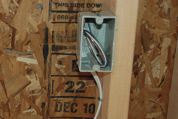
How to wire a wooden box with an electrical outlet. With one device added to the box, subtract two wires in each category. A quick and easy way to install electrical outlet boxesmore mastered in a minute videos: When obtaining the romex wire, determine the path of the wire and the distance from the new outlet to the electrical source, and then add 12 inches for each point of connection.
Create a hole for your outlet box. Make sure you have a snake or fish tape long enough to go from end to end. Best way to install an electrical box in an existing walltoday vince shows you how to install an electrical box in an existing wall for moving the outlet or.
Run wire in emt (electric metallic tubing) cut emt & tie wiring into existing power. Keep in mind that you can’t run more than 20a at once from single outlet due to switch rating (power = voltage x current). Install a circuit breaker on the wiring of the main electrical box.
Layout the pipe run adjacent to the trench. Push the box into the hole and ensure everything is snug how we like it! Push the conductors and about 1/4 inch of sheathed cable into the box and staple the cable within 8 inches of the box.
Tighten all the screws to hold the wires in place, then attach the subpanel cover. How to wire a shed for electricity: Make sure the cable clamp is holding all the wires securely in place.
In a system with metal boxes, the pigtail method is considered the most secure. If you damaged the wall around the box, use an oversize cover plate to hide the problem. Versión en español i found myself in need to move my noisy woodworking to my back yard to avoid waking up my lady who works night shift.
Use a keyhole or drywall saw to cut out the shape. Connect the neutral and ground to the brass terminal and ground terminal respectively. The grounding wire nut shown has a hole in its top that makes installing a pigtail easier.
A rotary hammer drill fitted with a carbide tipped drill makes an excellent tool, but if this isn't available, a star drill will work. In this arrangement both the receptacle and metal box are grounded. Glue or fasten the pipe together with approved fittings and adhesives.
Ground wires are spliced together and attached with a pigtail to the box and receptacle. For junction boxes installed on the ceiling, run the cable from the ceiling down into the box. Fasten the cable using a wire staple within 12 inches (30 cm) of the box to secure it.
Here’s how to install an electrical box without a stud using a winged remodel box: Trace a line to give a guide for breaking the block. Feed through enough cable to reach the new box plus an extra foot.
Mount the handy box in the desired location. Using a drywall keyhole saw, carefully cut the hole along the traced outline and remove. Feed new cable into the wall.
Position the electrical box backward against the wall, in the exact position you plan to install it. Thread the cables into the box and secure them. To do this, connect line 1 and line 2 to the lower hot terminals respectively.
If you're mounting it on a concrete, cement block, or brick wall, you will need to drill the wall using the appropriate size masonry bit (the one that came with the plastic anchor kit), drive in the plastic anchors, and screw the box to the anchors. Punch a hole (or two for two cables) through the knockout area of the box with a screwdriver or the point on your stripping tool. Break out the brick along the outline that you made using a cold chisel and a hammer.
Take a pencil and trace the outline of the box on the wall, avoiding the box's ears. use a utility knife to score the wall along the shape you outlined. Position the handy box & find appropriate fasteners. Drill holes at the corners of your outline and then use a ball peen hammer to break away the rest of the concrete.
Bring the wire to this location either by drilling up from underneath the floor, inserting the wire from the other side of the wall or running a metal conduit. I decided to wire my shed and after some homework and the help of the instructables community i s…. To wire the interior outlet, connect all the hot wires (black and any other color except green or white), all the neutral wires (white) and all the ground wires (green or bare copper.
The switch should be inside the house for safety reasons. Trace the outline of the box onto the wall. In this article, we will take a close look at the intricacies involved in.
Strip the wires with wire strippers. Start with one wire and strip off 3⁄4 inch (19 mm) of casing insulation at the end. Gently fold the wires into the box, then reattach the outlet and cover plate.
Also you will be able to turn off the electricity when you leave for vacation. Connect the red and black wires to the two screws on the hot bus strip of the subpanel. Attach an appropriate emt termination.
Fluke 3000 fc hvac system lets you work on electrical panels faster,. Dividing this number by the change rate gives the required airflow in cfm.
Digital Pro Cfm Anemometer Hvac Wind Speed Meter Air Flow Velometer Temp Tester | Ebay
Sale $ 854.99 $ 949.99.
Cfm meter hvac. For users who prefer to calculate their. The sc260 is the best fieldpiece multimeter available. In the world of hvac, cfm stands for cubic feet per minute.
Hvac equipment operated at higher air speeds than those for which it was designed loses efficiency and for filters, will begin to bypass rather than remove particles from building air. The calculation for cfm involves dividing the total volume of the space by the air exchange interval. The unit used to express this air change rate is the ratio of cubic meters per hour and the volume of air within the room.
Fluke 922/kit was designed and built for how (and where) you do your job, with performance,. With a resolution of 0.01, measurements in ohms, voltage and amps, you won’t have any trouble finding the fault in the hvac system. This video demonstrates two simple methods of measuring airflow in hvac systems to optimize the performance, efficiency and comfort that is too often comprom.
For example, if a kitchen is rectangular with a width of 10 feet and a. One of the basics of general hvac is simple unit conversion. Meanwhile, a 100x300mm duct at 1 meter length has an area of 0.8m 2.
They give you an economical solution when it comes to reporting and controlling air flow, providing quick or constant measurements of your hvac system. In most cases, these are either metric or us standard units. Speed values from air supply or return vents in residential or commercial buildings with professional grade air flow meters from cps products.
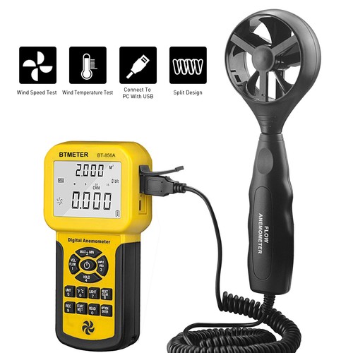
We deal with btus, watts, volts, amps, ah, wh, °f, °c, cfm, kw, hp, eer, seer, ceer ratings, and so forth. The ir function allows you to test temperature without making contact, while the type k temperature function. Air flow (volume) to 9900 cfm/cmm, and air temperature 122°f/50°c) for use in hvac system installation and maintenance, cleanrooms, kitchen exhaust systems, wind power monitoring, construction, sailing/boating, vehicle aerodynamics, and many.
+91 80 678 77200, singapore: 3.7 out of 5 stars 8. In short, we get the same number.
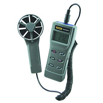
Air flow rate, or quantity of air being moved, is measured in m 3 /sec (cubic meters per second) or cubic feet per minute (cfm). To calculate room volume, you measure its length, width and height in feet and multiply these. The triplett model cfm100 anemometer measures air velocity up to 5900ft/min (30m/s), air flow (volume) to 9900 cfm/cmm, and air temperature 122°f/50°c) for use in hvac system installation and maintenance, cleanrooms, kitchen exhaust systems, wind power monitoring, construction, sailing/boating, vehicle aerodynamics and
The cost of a duct is heavily dependent on the total area of the duct. Simply put, it is the number of. Here at learnmetrics, we try to answer the most common ones to help everybody with a better understanding of hvac.
Alnor products, tsi incorporated, website: Fluke 3000 fc hvac system. Notes to the table above.
A temperature sensor in the probe tip compensates for air temperature, a sensor in the meter reads absolute pressure, and ambient absolute pressure is determined upon meter initialization. Air flow cfm master ii meter and tester for hvac (dcfm8906) 15% less. Whether you need easy installation or a digital display for readings, johnson controls has a meter for you.
Holdpeak 846a pro anemometer wind speed meter cfm cmm air flow temperature. It is a measure of how much air can be moved in one minute. Cfm = (1,000 sq ft * 8 ft * 4) / 60 min = 533 ft3/min = 533 cfm.
$4.00 coupon applied at checkout save $4.00 with coupon. You can check this list to get an idea of how much cfm the best air purifiers can produce (for reference). Air velocity meters use vane, cup, hot wire, or differential pressure technology to measure the speed and/or volume of air movement.
Shop triplett digital anemometer specialty meter in the test meters department at lowe's.com. Cfm is the amount of air that moves through an area in one minute. 4.3 out of 5 stars 217.
Whether you are just learning how to measure air flow or you are an experienced hvac technician, indoor air quality technician, or energy efficiency consultant, our meters provide air velocity and air volume flow readings as well as useful indoor air quality metrics. Air flow meters are perfect for taking accurate measurements of velocity and pressure. Ex623 makes for a perfect hvac tool, offering ac/dc voltage and current measurements, as well as resistance, capacitance, and frequency measurements.
Get it as soon as thu, feb 3. For instance, a 100x200mm duct at 1 meter length has an area of 0.6 m 2. Where to buy air flow cfm measurement devices for hvac systems.
They are commonly found in weather stations but are also important tools for analyzing ventilation systems, aerodynamics testing, hvac balancing, fume hood verification, and other applications in which the movement of air is a primary concern. You can freely use the cfm calculator to calculate airflow for. Get it by thursday, jun 2.
The fluke 975 airmeter tool has an accessory velocity probe that uses a thermal anemometer to measure air velocity. Bypass air is used in some heat pump systems to control system performance and economy by sending some air around rather than through the cooling or.