Solder is heated until liquid and then added to the. The western union splice connects two conductors together and is particularly useful in repairing a broken wire.
Electrical Symbols Of Circuit Components - Electric Circuit, Components With Symbols, Video, And Faqs
Components to make electrical connection.;

Joining electrical components. A properly done cemented joint is permanent and both airtight and watertight, and it takes less than a minute. Components used to resist current.; The electrical conductivity is fairly limited (so they are not a good replacement for solder).
The solder metal has a lower melting temperature than the working piece. The male component, called a plug, connects to the female component, or socket. Even when a hot line switch is off, one terminal on the switch is still connected to the power source.
An example of solder joints was shown in chapter 2 for the cordless telephone. Most connectors are removable or temporary, but some can be permanent. Authors sebastian micus 1 2 , michael haupt 1 , götz t gresser 1 2 affiliations 1 german institutes for textile and fiber.
Joining materials and components soldering. Remove any oil, paint, wax, etc. Solder paste is used to join electrical components to printed circuit boards to create an electronic circuit.
The two wires are trimmed of insulation, then each is wrapped around the other around six times. To solder, heat the connection with the tip of the soldering iron for a few seconds, then apply the solder. Connectors make electronic products easier to assemble and manufacture.
Popular standards such as iec, bs en, ul& is are followed to manufacture and to test these connectors. Ceramics are an incredibly diverse family of materials whose members span traditional ceramics (such as pottery and refractories) to the modern day engineering ceramics (such as alumina and silicon nitride) found in electronic devices, aerospace components and cutting tools. The method is called a western union splice where you.
Hold the soldering iron like a pen, near the base of the handle. Electrical components in a building can easily cause an electrical shock, burn, or even death. The soldering process is done in various.
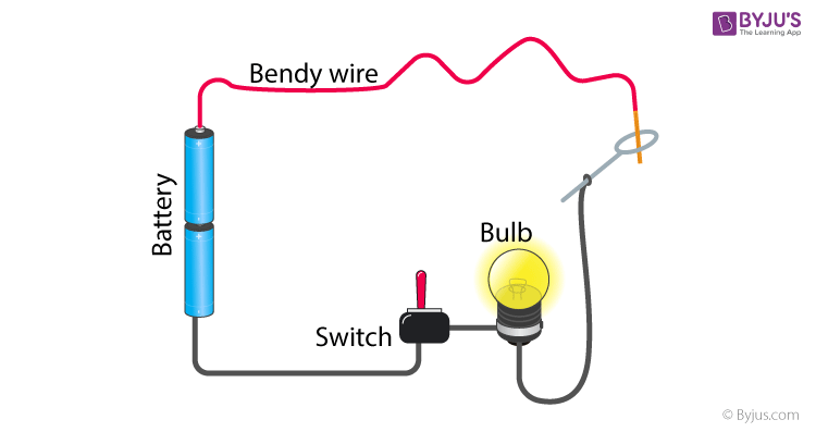
It is a combination of cells and its utility is the same as the cell. Below is a brief overview of the components and their functions. When building electronic circuits, you will work with a number of basic electronic components, including resistors, capacitors, diodes, transistors, inductors and integrated circuits.
They also ease circuit repairs and allow flexibility in design and modification. The type of flux to be used in soldering depends on various factors such as type of pcb to be assembled, type of electronic components used, type of soldering machine and equipments used and the working environment. By liam.plybon.3 in circuits soldering.
These products are compression or bolted type. Volume resistivity is typically about 0.09 ohms∙cm. Before doing any work on the switch, the power source must be turned off by setting a circuit breaker to off or removing a fuse.
Electrical connectors are devices that join electrical circuits together. An electrical connector is an electromechanical device used to create an electrical connection between parts of an electrical circuit, or between different electrical circuits, thereby joining them into a larger circuit. Function of basic electronic components.
Joining electrical components with rubber tubing. The western union splice, the tap splice and the fixture splice. Joining electrical components with rubber tubing.
Heat the connection, not the solder. In its symbol, the larger terminal is positive, whereas the smaller one is the negative terminal. And are sometimes used to join structural components.
The soldering process can be applied in electrical and electronic projects, plumbing, etc. Be sure to strip enough insulation from the wire to allow for several twists between the two pieces of wire. Automatic joining of electrical components to smart textiles by ultrasonic soldering sensors (basel).
Electrical continuity of the composite and arcing between fasteners. Soldering is the process of fixing one or more components as one by one by dissolving and running a solder in the joint is called soldering. They are used extensively on circuits for.
Solder (wire, bar, paste, balls, preforms) solder is the life and blood of any pcb assembly. There are three main types of electrical joints, also known as splices: If you can't use solder to join your wires, a splice that winds the wires together will get the job done just as well.
A resistor is one of the components you will come across in an integrated circuit. Possible galvanic corrosion at the composite joint. Solder paste is smeared, by hand or robot, over the surface of a stencil that has been placed over a circuit board.
Soldering can be done by hand or automated by machine. Physics major at a&m university getting into astrophysics research this year. With a solvent, steel wool, or fine sandpaper.
A quick demonstration on how to join up the electrical wire when cutting it and adding an extension. In this section, let us learn about some important circuit diagram symbols. Components that may be made to either.
Pick and place assembly is when components are picked up and placed on a circuit board. These components are those that have gain or directionality. Transistors, integrated circuits or ics, logic gates.
The best way to splice wires is to wrap them together tightly, using multiple twists to. The solder paste is pushed through holes in the stencil onto metal pads on the. It provides the source of current.
They can hold the electrical and low voltage wires. Low voltage is defined as 50 volts (v) or less.
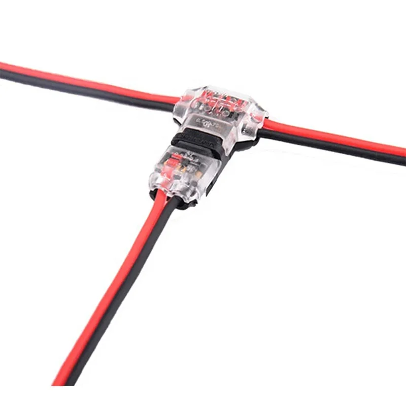
2 Pin 2 Way Low Voltage Universal Compact Wire T Tap Connectors Toolless Wire Connectors Quick Splice Wiring Connector - Buy Low Voltage Wire Connectors,Low Voltage Landscape Wire Connector,Electrical Connectors Low Voltage
Pin 2 (most common) the jst is a popular r/c connector, and is well suited for battery packs, containing an internal lock and a polarized connection.

Low voltage electrical connections. Getting this wrong is likely to damage electric circuits. Age and corrosion are a common cause of low voltage, as is dirty connections and poor insulation. Inside column for low voltage electrical connections.
Connection and livening guide issue date 9.08.2013 nw72.15.02 amendment no.4 2 of 23. Common low voltages are 12v, 24v, and 48v. Measuring low voltage networks while under voltage separation filters (400v) enable the direct connection of a reflectometer on the low voltage network while under voltage.
Connection of electricity supply may be delayed or withheld and installations with supply may Three things to consider while you’re installing a low voltage structured cabling network are: Benito navazo juan manuel (es) assignee:
Because it’s separate, an experienced wiring contractor who specializes in low voltage wiring is essential during new home construction. Generator set serving common loads. As with any wiring installation, you should make sure that your clients won’t have to deal with the adverse effects of an improperly installed wiring network.
In some cases, the wires used to carry electricity have a lower gauge than is necessary. The type of low voltage connector. Most modern low voltage distribution systems are operated at ac rated voltage of 230/415 v at 50 hz in india and 120/208 v at 60hz in usa.
Pin 1 (most common) positive. Ac circuits have no polarity. Service work) supplied from that network.
They will be able to efficiently build an infrastructure that supports the standard needs of most modern homeowners as well as ensure it can scale up to handle any additional electrical upgrades in the future. The international electrotechnical commission (iec) defines supply system low voltage as the voltage in the range 50 to 1000 v ac or 120 to 1500 v dc in iec standard voltages which defines power distribution system voltages around the world. Low voltage is normally used for doorbells, garage door opener controls, heating and cooling thermostats, alarm system sensors and controls, outdoor ground lighting, household and automobile batteries.
If low voltage wires need to cross electrical wires, they should be done so at 90 degrees. Jst rcy connector (continued) also known in rc circles as the bec connector, or the p connector, it. The international electrotechnical commission (iec) and the uk iet (bs 7671:2008) define an elv device or circuit as one in which the electrical potential between.
Connection is defined as the prescribed electrical work (pew) that is the final step that will allow electricity to flow in the installation or part installation on which other pew has been done. This includes chemicals mentioned, as reported by pubchem. The type of power, ac or dc.
The voltage level of lv distribution system is typically equal to the mains voltage of electrical appliances. Let’s see four most common designs for connecting generator set (s) to the low voltage systems: The female (plug) is usually used on the battery pack.
Poor or damaged splicing work can also be a cause. Avoid running low voltage wires parallel to electrical wires. The term commonly used is polarity, for dc circuits;
The plus and minus position. Use these boxes at every location where a tv is going to be mounted to the wall. The measurement should always be performed from the cable end or service box in the direction of the supplying station.
Usually, low voltage wiring helps digital technology and communication equipment to function correctly. Low voltage electricity installations infrastructure management nw72.15.02. Generator sets are commonly provided with a main circuit breaker that is mounted on the generator set and service to loads is provided through a separate distribution panel as shown in figure 1.
Aparellaje electrico sl (es) date: Secondary networks are operated at a low voltage level, which is typically equal to the mains voltage of electric appliances. Section 82 (4) of the electricity act 1992 allows connection for the.
10 amazing low voltage wiring connections 2021. Gm1263734234 $ 12.00 istock in stock However, due to this high electrical resistance, these oxides must be broken or removed before making up connections.
Electrical low voltage combo box. It is a specific electrical network foundation that uses less energy to run and, in return, saves budget and electricity. If a city of 200,000 people is properly wired, a sudden increase in population will strain the system.
Connectors and wires have limits which should be exceeded. Actually, low voltage definition depends on electric equipment, country standards. Figure 1 typical 230/400 v three‐phase supply.
Low voltage is supplied by batteries. Temporary connection for the purposes of testing may have already taken place. Most modern secondary networks are operated at ac rated voltage of.
It shows you what a basic circuit looks like and even shows you how to add a switch to a light w. These wires are color coded for easy identification.

House Wiring Images, Stock Photos & Vectors | Shutterstock
Grounding wires are used to protect people and appliances from shock, in the event, it contacts any conductive part of the frame.

Electrical wiring work. Make sure you take electrical wiring layout from the contractor for any future changes in electrical wiring. Current enters a circuit loop on hot wires and returns along neutral wires. Wiring is subject to safety standards for design and installation.
Electrical work & repair costs. It is similar to the block diagram except that various electrical elements such as transformers, switches, lights, fans, circuit breakers, and motors are represented by standard schematic symbols. Diversity factor in electrical wiring installation.
Full pdf package download full pdf package. For larger electrical jobs like installing wiring or replacing an electrical panel, expect to pay $2,000 to $6,000. Means any labor or material used in installing, altering, maintaining, or extending an electrical wiring system and the appurtenances, apparatus, or equipment used in connection with the use of electrical energy in, on, outside, or attached to a building, residence, structure, property, or premises.
The average cost to hire an electrician to install or repair light fixtures, outlets, switches, or fans ranges from $141 to $419 with homeowners spending $280 on average. Electrical wiring is a process of connecting cables and wires to the related devices such as fuse, switches, sockets, lights, fans etc to the main distribution board is a specific structure to the utility pole for continues power supply. The bare wire, green or green with yellow tape wires are the grounding wires.
Report on electrical wiring accessories introduction : Green grounding wires should always connect to only other green grounding wires. Wire sizes range from about 22 gauge to 12 gauge.
Most residential service includes three wires: The service entrance is the equipment that brings electrical power to the home. What is a wiring diagram?
He worked as an electronic technician and later an engineer for the ibm corp. Electrical wiring whether for residential. Electrical wiring in general refers to insulated conductors used to carry electricity and associated devices.
General aspects of electrical wiring are used to provide power in to building and structures commonly referred as building wiring. Emt that's long enough to reach an easily accessible box in the basement or crawl space. Electrical wire and circuit breakers are designed to work in tandem with one another, and each must be of a proper corresponding size.
Check out what others are sharing at ask the electrician: Several factors are to be considered before doing the actual installation work whether for commercial, residential or. It consists of symbols to represent the.
It shows how the electrical wires are interconnected and can also show where fixtures and components may be. Trip to break the electric circuit and stop flow of electricity. Make wiring distribution for all rooms from flooring, concealed wiring from flooring makes work faster and easy.
For safety, all modern circuits include a. Manual ups wiring diagram with change over switch system. Automatic ups system wiring circuit diagram for home or office (new design with one live wire) automatic ups system wiring diagram in case of some items depends on ups and rest depends on main power at office or home.
The following is sort of an electrical wire types chart: This wire returns the current to your electrical circuit. Avoid wire looping from one point to another for durability and of course safety work.
A wiring diagram is a simple visual representation of the physical connections and physical layout of an electrical system or circuit. 18 rows other important electrical wiring symbols. He electrical wiring scope must cover installation, testing, supply and commissioning of all accessories, wiring, switches, conduits, spur outlets, and many more.
Room for full size circuit breakers for all your circuits. The complete guide to electrical wiring. Black wires or “hot wires” carry live electrical loads from the electrical service panel to an outlet, light or other.
Allowable wire and cable types and sizes are specified according to the circuit operating voltage and electric current capability, with further restrictions on the. The term includes service entrance conductors as defined by. Planning of wiring work features of electrical wiring examples of lighting circuits schematic wiring examples of socket outlets schematic wiring final circuit for 13a socket outlets 7 7 10 15 17 18 4.
Get free estimates from electricians near you or check out our pricing. Start by drilling a small hole with a long bit to make sure you're in the right spot. Several common types are landscape lighting wire, sprinkler system connections, bell wire (for doorbells ), speaker system wires, and thermostat wires.
Methods of electrical wiring systems w.r.t taking connection A short summary of this paper. Correct amperage for all loads and future requirements.
Two cables carrying 120 volts each (for a total of 240 volts) and one grounded neutral wire. For example, 14/2 gauge electrical wire is rated to a maximum of 15 amps and should not be used with any circuit breaker larger than 15 amps.12/2 gauge wiring is rated to a maximum of 20 amps. Control and protection system for electrical wiring 19 4.1 4.2 4.3 selection of control and protection system for electrical wiring
Hot wires are black or red, and neutral wires are white or light gray. If they are routed underground, they are known. Residential electric wiring diagrams are an important tool for installing and testing home electrical circuits and they will also help you understand how electrical devices are wired and how various electrical devices and controls operate.
Red wires are also hot wires used to interconnect smoke detectors, so that if one alarm goes off, all the others do as. Thus, electrical wiring needs further attention, especially for building projects. If the cables are hung overhead, they are collectively called a service drop.
Electrical wiring is an electrical installation of cabling and associated devices such as switches, distribution boards, sockets, and light fittings in a structure. 6 full pdfs related to this paper. Is a member of the spruce home improvement review board.
Larry campbell is an electrical contractor with 36 years of experience in residential and light commercial electrical wiring.
Why do we camera electrical lines? Evaluate if the workers are knowledgeable on.

20Mm White Pvc Conduit Inspection Elbow – Sed Electrical Products Ltd
During the inspection, certified electricians will check the safety of all electrical devices in your home by following a checklist.

Electrical conduit inspection. This document defines the methods to be used to ensure that the electrical works to be conducted at a project site are in compliance with the approved designs and approved materials. Verify pvc coating, threaded lubricant is applied. A small conduit for network/phone.
Conduit in place should be fine for the inspection. The forces involved in pulling make doing so without the conduit buried (so it stays put) rather difficult, and in any case it's quite common (and it you have not, i suggest you go get some) to put empty conduits in a trench for future use (i.e. Use this template to assess the compliance of electrical safety measures for a given worksite.
The complete table of inspection and testing activities that shows each activity to be performed in order to make sure that the installed cable trays, ladders & conduit are compliant to the project’s specifications and requirements, the reference to be followed, acceptance criteria, responsible personnel, related checklist (from item # 3. Do a site walkthrough and inspect the electrical tools and equipment being used (e.g switches, power lines, appliances, installations, wiring, cables and cords). General information 1.1 purpose 1.2 scope of work 1.3 references 1.4 location 1.5 definitions 2.
To be made after trenches or ditches are excavated, conduit or cable installed, and before any backfill is put in place. Emt conduit and fittings carbon steel galvanised tube , electrical metallic tubing. Conduit protects both humans and the electrical wiring to prevent wires from pulling loose and creating shock hazards.
Boxes and conduit bodies item inspection activity nec reference comments 1. We include ips for installing & inspecting electrical conduit in homes and electrical conduit cutting, bending, installing suggestions. Of bends and lengths of the straight run as specified.
Stand out from the crowd by offering the home inspection industry’s strongest guarantee. This takes place when you have installed all of the electrical boxes, cables, conduit, and wires to the point that you are ready for the walls to be closed up by surfaces. March 15, 2021 by engineer calcs.
You’ll learn about the main types of electrical conduit and their applications. Hot dip galvanized emt conduit and fittings with american standard steel set screw coupling. We can even inspect your fiber ducts and help you.
Electrical conduit guide with 10 tips & tricks. Conduits are used to provide extra protection for electrical wires. Using advanced robotic technology we can assess the structural integrity of your conduits in concrete, clay or plastic.
Fix conduits in between concrete nails in block wall and tie with binding wire rigidly to avoid change in conduit layout. This will include, among other household components, inspecting. Electrical wiring conduit defects found by visual inspection.
So, i’ve made this beginner’s electrical conduit guide with added tips. When concrete gets in the inspection box in electrical wiring.it can block the pvc electrical conduit pipes. Conduit boxes shall be installed in the block walls as per specifications and approved shop drawings.
You lay electrical conduits in concrete slab, by connecting the conduit pipes to the boxes. Before you can install and inspect electrical conduits, you need to know the basics. If you will be excavating, trenching or installing electrical conduits, also see the specification for installation of underground conduit systems (crl 1669).
It’s important to use conduit even for buried wires to prevent damage to wiring from digging and moisture. We cctv electrical conduits to verify to the contractor and regulators that the electrical conduit is fit for purpose and not going to cause costly damage to. Pvc patching compound must be on sleeves.
The checklists are in pdf format and can be completed electronically or printed and used as hard copy. An electrical conduit inspection is a cctv video recording of the inside of an electrical conduit looking for structural defects, sharp edges, or debris. Almost all conduits are available in different sizes.
Internachi inspection image gallery / electrical / conduit conduit home inspection images rigid metal conduit member marketing forum find an inspector take our exam certification & licensing become a cpi. After you are done filling the boxes with soaked paper or whatever material that you want to use. In these instances, an electrical inspector will need to visit you on at least two occasions.
Verify that the conduit is properly supported. Electrical conduit camera inspection services. With my experience as an electrical expert on personal injuries with a law firm and having worked as an electrical inspector, i truly see the need for a workbook such as this.
This pdf contains 77 electrical inspection checklists taken from the 2014 electrical inspection manual with. After installation inspection approval, finish with concrete cement, plastered flush with the wall surface. The pull box minimum length will be the size of the largest raceway or conduit x 8.
Installation shall permit easy drawing in of cables. Here i must mention that when joining. This guide contains 77 most important electrical inspection checklists taken from the 2014 electrical inspection manual with checklists.
Let us show you how inspecting your conduits and ducts before you pull new cable can reduce outages, and save you time and money. Your electrician will check to see if you have the correct number of circuits to serve the demand of your home—this is especially. If our inspection is limited to an external, visual inspection of electrical conduit, we may not immediately be able to see safety and electrical code violations such as use of improper wire type or too many wires in a conduit, but here are some easy to spot concerns that merit.
The method of statement covers the procedure for material delivery inspection, installation and inspection of pvc conduit embedded in wall, false ceiling or slab.… Identify wet and damp locations and the suitability of boxes and fittings. Execution 2.1 materials and tools 2.2 manpower 2.3 procedure of work 2.3.1 pipe installers 2.3.2 handling & storage 2.3.3 conduit fitting 2.3.4 assembly & joining 2.3.5 under ground conduit 2.3.6 trenching, bedding & backfilling 2.4 responsibilities 2.5.
Use this work procedure as a guide to help you inspect conduit as follows: Electrical metal conduit galvanized steel bs4568 tube gi pipe
Equipment grounding will prevent equipment as cabinet enclosures and motor cases from becoming charged to a potential that could be. The fundamental purpose of electrical grounding is to both protect personnel as well as property.
Need For Earthing And Double Insulation - Mini Physics - Learn Physics
Electrode conductor connected to the grounded service conductor — at each service — according to 250.24(a) of the code.

Double grounding electrical. I quote from the black & decker rotary drill manual: It is the true zero reference for any and every electricity discussion. The ground bar is bonded internally when an external bond to earth is installed as described at the link for electrical grounding below.
Earth electrodes are made of copper, galvanised iron, cast iron etc. So double grounds in the sub panel. #4 get rid of the panel, it doesn't comply with ul rules and was never ul listed in the first place.
The neutral bus won’t be bonded. Ground wires for residences typically are made of copper and are #6 (6 awg) or larger. Osha regulation 29 cfr 1926.404 (f) (7) (iv) states that electric power tools must be grounded except when they are double insulated.
They are usually copper plated steel with a connector called an acorn at the top to hold the ground wire to the rod. #4 copper wire is sufficient for service not exceeding 200 amps. Electrical circuits may be connected to ground for several reasons.
Bonding insures that if there is any stray electricity it will be directed to the ground. Household electrical systems are required by the national electrical code to have a grounded system connected to earth ground via a ground rod. Grounded vs grounding zgrounded vs.
It will limit the voltage imposed on the. Follow edited may 17, 2021 at 4:30. Determine the amperage rating of your electrical service by looking at your main breakers.
When properly done, current from a short or from lightning follows this path, thus preventing the buildup of voltages that would otherwise result in electrical shock, injury. Asked jul 18, 2020 at 12:44. Grounding (earthing) is a system of electrical circuits that are connected to the ground that functions when a leakage current can discharge electricity to the earth.
The term ground refers to a conductive body, usually the earth. 250.24(a)(1) of the code allows this grounding connection (earth connection) to be at various locations. A conductor buried in earth for the purpose of electrical earthing is known as earth electrode.
71.8k 24 24 gold badges 109 109 silver badges 200 200 bronze badges. Article 100 of the nec defines ground as “the earth.”. The difference between a service panel and a sub panel is also muddy in many minds.
Ul requires there be enough neutrals and grounds. Grounding in an electrical system. This is the double pole service disconnect, this is also called the “main.”.
According to institute of electrical and electronics engineers (ieee) standard 142 ™ 2007, the purpose of the grounding system is to: Exposed conductive parts of electrical equipment are connected to ground, to protect users from. The ground wire, often referred to as the grounding electrode conductor, is the link between the ground rod and the service ground connection.
These rods are eight feet long, driven into the ground. The topic of grounding and bonding is a never ending area of confusion. An electrical ground prevents conductor voltages from exceeding the rating of the respective conductor insulation.
Do not use any adapter plugs with earthed (grounded) power tools. The system amperage (usually 100 or 200 amps) determines the required gauge of the bonding wire you need. Grounded system refers to a system where a conductor is grounded and is intended to or may carry current in the normal operation.
Basically, this is saying each building that is served electricity shall have its service connected to the earth. Zthe grounding conductor system is not Continue to 5 of 5 below.
Could someone please explain why power. The neutral on a wye system is a prime example of a grounded conductor. In electrical engineering, ground or earth is a reference point in an electrical circuit from which voltages are measured, a common return path for electric current, or a direct physical connection to the earth.
Proper grounding is a critical safety measure in all electrical systems and installations. Earth ground is true zero volts. The shape of the earth electrode may vary from conductive rod, conductive plate, metal water pipe or any other conductor with low resistance.
Smaller, less expensive copper wire is allowed for services between 100 and. (double terre) in the tt system, the. Grounding is the electrical system’s connection to the ground itself.
#2 get a separate ground bar and move the grounds to it. For 200 amp services, a #4 grounding electrode conductor (ground wire) is required.