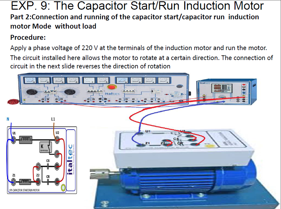
These motors are called capacitor start capacitor run motors. Wiring diagrams seem to suggest that voltage energizes the hot leg of the circuit and current flows through the run windings and then returns via the neutral leg.
Solved Part 2:Reversing The Direction Of The Capacitor Run | Chegg.com
Century condenser fan motor wiring.

Capacitor start capacitor run wiring reverse 220 volt. Look at the wiring diagram for your specific hvac equipment and find the. 240v motor wiring diagram single phase collection with capacitor electrical electric nest thermostat manual pdf compressor circuit. Motor run capacitor 660 volt ;
When you use your finger or perhaps follow the circuit along with your eyes it s easy to mistrace the circuit. Motor run capacitor 370 volt ; Voltage rating of the motor.
Motor run capacitor 440 volt ; Check the voltage between the output legs of the pressure switch. The reconnection must be done with wires that are not now coming out of the motor.
You will then have a good idea where the fault is. I don't understand the direction of current flow when a capacitor is wired in series with the start windings in, say, a fridge or other ac motor running at/under 120v ac. Click on the image to enlarge and.
I think think your start an run capacitors are connected correctly. You can reverse a 240 volt single phase motor with start capacitor by reversing the leads to the start winding. I would have expected the resistance reading between yellow and blue wires to be almost zero ohms.
How to change rotation on a dayton 120 volt ac motor. Single phase capacitor start motor wiring diagram. The questions & answers below discuss the wiring connections for electric motor start / run capacitor wiring as is typically found on heating & air conditioning systems as well as on other electric motors such as well pumps, sewage pumps, and electric shop tools.
For instance , if a module is usually powered up and it sends out a new signal of half the voltage and the technician will not know this, he would think he has a challenge, as. Home > capacitors > motor start capacitor 220/250 volt. Swapped the white and black over and connected the black to the white wire and the white wire to the brown wire which goes to the field winding in the motor.
If you put the machine in forward and it is actually running in reverse, swap the t5 and t8. For motors that can be wired at both 120 volts and 240 volts, the starter winding is a 120. Regardless of what you need it for you can usually find a list of.
Is 115 volt a single breaker or 220. Drum switch usage 220 volt single phase motor: Rotation direction of the motor.
If a motor is dual voltage 115/230, then it has a 115 volt start circuit and start cap. When the motor is connected 230, the start winding is connected to the center of the run winding, so it is st. Push the wire terminal on the start capacitor's second wire onto the run capacitor's common terminal, often labeled c, com. the wire connected to the motor's run terminal, marked as r on the motor's wiring chart, and the wire going to the hot terminal on the load side of the contactor also connects to this run capacitor terminal.
This one is 1.75 horsepower. Motor start capacitor 220/250 volt. A ge 3/4 hp capacitor start/capacitor run, two wires have to be switched in order to reverse.
To properly read a electrical wiring diagram, one offers to learn how the particular components in the system operate. Run capacitor rating (mfd rating) of the motor. Motor start capacitor 330 volt ;
I will try to post a sketch. I'm looking for a schematic to wire a dayton 31tr76 motor at 240v to a dayton 2x440 reversing drum switch. Capacitor volt rating depends on the start winding voltage, not the line voltage.
Now i want to run it forward. Wiring a single phase 230 volt 6w variable speed panasonic spur motor: To reverse rotation on a single phase capacitor start motor, you will.
The horsepower rating of the motor. The wires to reverse are always the wires that lead to the starter winding. Reversing single phase induction motors.
Single phase motors are used to power everything from fans to shop tools to air conditioners. Start run capacitor wiring diagram and kwikpik me motor circuit 1440 best of starting electronic projects water pump 2003 toyota tacoma trailer mitsubishi colt t120ss. Capacitor start capacitor run motors are typically more than one horsepower.
How can i connect a 5 hp 220 volt reversible capacitor start motor to a selector switch for forward and reverse. How to wire a run capacitor to a motor | some capacitor and motor wiring factors include: To answer this question correctly you need to give more information about the motor and the switch, to switch the direction of the motor you must reverse the polarity on one of the windings, to be able to do so the motor and the switch need to.
There ll be primary lines which are represented by l1 l2 l3 and so on. 230 volt single phase motor wiring diagram. Very often a capacitor is used.
I have cut the start winding wires being the thin one and attached a insulated wire and run it into the terminal box on the motor. Check the voltage between the input legs of the pressure switch.continue back towards the mains supply until you get 220 volts. Now i have 2 ends of the start winding.
Wiring a single phase motor with capacitor. Why is a capacitor not used in a single phase motor? When i wired up 30 years ago i could never figure how to wire it for forward and reverse.
A motor with a start and run capacitor and a start and run coil. Diy how to wire single phase 115 volt electric window ac unit blower motor with start run permanent capacitor wire for testing purposes only i needed a. Work back from the output side of the pressure switch.
The fact that it is over the same wires doesn’t ‘matter’ if the wires are sized properly. This item is in the category “home & garden\home improvement\electrical supplies.

1500 W Turbin Angin Grid Tie Inverter, 3 Phase Ac 45 90 V Input Ke Grid Ac 220 V, 230 V, 240 V|Tie Inverter|Grid Tie Invertertie Grid Inverter - Aliexpress
Can i tie the neutral and ground together?
240 volt tie. C) not obscure the ampere marking on either circuit breaker. Then 240 is split at the main panel into two 120 volt circuits, which feed wall outlets and lights. This item is in the category “home & garden\home improvement\electrical supplies\alternative energy supplies\alternative energy chargers & inverters”.
@ 208 volt 3 phase that would be just less than 5 amp's per phase. Handle ties, when installed, shall: 7.6kw 240v grid tie inverter by solar edge battery backup additions possible.
Your inverter is ‘feeding’ 240 v to the utility. In this post, you can read more on the difference between 220 and 240 volt outlet. The seller is “xtentsales” and is located in salt lake.
10kw single phase grid tie solar inverter. Posted may 30, 2022 by admin in category sunny. Removing all obstructing objects like furniture, cabinets, and shelves.
A) operate both circuit breakers when either circuit breaker handle is manually operated; Mars is right, usa residential power consists of homes being fed by single phase 240 volt. 120 and 240 volt circuit breaker lockout fits standard height and tie di tokopedia ∙ promo pengguna baru ∙ cicilan 0% ∙ kurir instan.
Has been fully tested on a solar system and it’s in perfect working condition. The high draw appliances like clothes dryers, water pumps, hot water heaters, hot tubs and such are typically fed at the full 240 volts via a two pole breaker. I plan to eventually run a second 240 volt outlet when i have the time and consider this a temporary solution.
Carefully cutting a hole in the drywall to receive the outlet. Inverter includes the hardware required for. Follow edited jun 5, 2014 at 10:08.
Your home is using 120/240 volts from the utility. @ 240 volt split phase that would be 12.5 amp total. However, plugging a 240 volt kiln, for example, into a 220 volts circuit will result in slow firings.
Superior efficiency at up to 98%! Determining of the best location for the new 240v outlet. Shutting off power at the main breaker.
Split phase system is defined as having 2 x 120v hot wires (normally denoted as l1 and l2 and. Now the wire for ground needs to run through similar bar. There are some scratches and scuffs from previous use.
These are the general setup and may vary and depend on the installation e.g. Modified sine 24 volt inverters (2) modified sine 48 volt inverters (1) modified sine inverters (26) 12 volt inverter chargers (1) 12 volt inverters (18) 24 volt inverters (2) Leading high efficiency ensures high energy yields of a home system.
@ 120 volt that would be 25 amps for a single phase. 128k 76 76 gold badges 305 305 silver badges 587 587 bronze badges. No, the neutral and ground should never be wired together.
This is wrong, and potentially dangerous. When you have a 3000 watt inverter to feed into the grid: Psi10kd 48v stackable 120/240 volt split phase 10000 watt inverter can support 120v/240v split phase output which is the main power standard used in north american countries including us, canada, mexico, costa rica, ecuador, panama, and venezuela markets.
Installation of 240 volt outlets usually includes the following steps: Neutral wire may be needed for three phase 240v outlets etc. Micro on grid solar inverter features maximum power point tracking and power automatically locked functions, making efficiency higher than.
Generally, for a inverter that is going to be used for residential use, the output voltage is rated at 240 volts alternating current (vac), whereas commercial inverters can range from 208 to 600 vac.